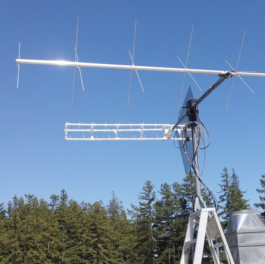
The SlugSat satellite itself will have 7-meter long half-wave dipole antenna for HF transmissions, as well as a 70cm half-wave dipole for telemetry at 435MHz. At the ground station on the UC Santa Cruz campus, we have a helical antenna and a beam antenna with zenith and azimuth tracking capabilities.

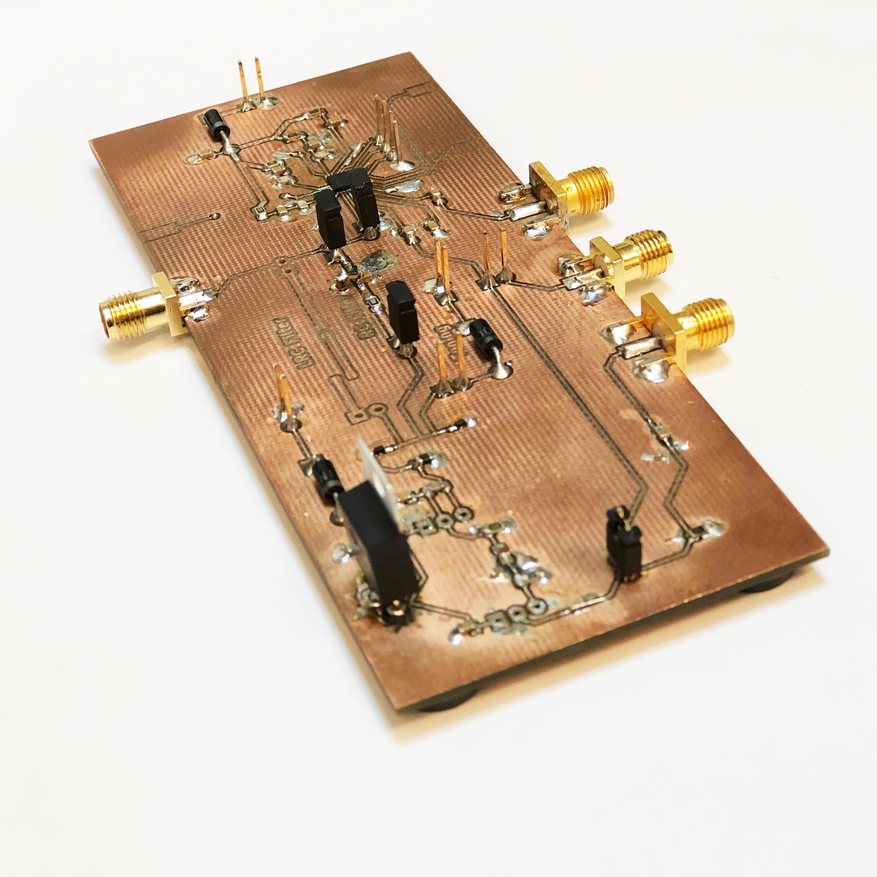
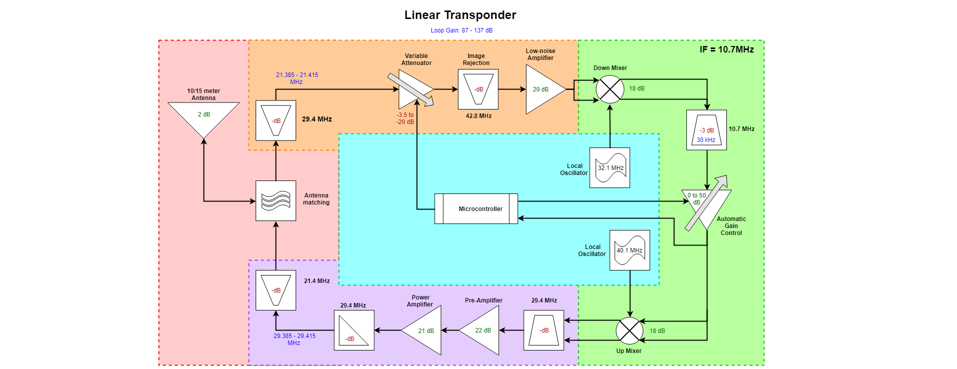
All circuitry in the linear transponder is designed and built from scratch by students. For more details on the design of the system, refer to the block diagram below.
Our mission calls for a method of long distance communication between two amateur radio ground stations working on the high frequency RF bands on Earth’s surface. The standard payload on many existing satellites to facilitate radio communication is a linear transponder. Linear transponders act as a relay between ground stations, as they receive message signals on one frequency and then automatically re-transmit them on another frequency. In order to use this relay for long distance communications, the transponder must have a large footprint. A footprint is what we call the surrounding area on the Earth in which the transponder can reach. Since footprints are limited by the transponder’s line-of-sight to Earth’s horizon, higher elevation transponders have larger footprints. By flying these transponders on satellites in Earth’s orbit, the transponder has the highest possible elevation and thus a large footprint. Any two ground stations in this footprint can communicate with each other via the satellite, thus providing the long distance communication link. Due to all of these reasons above, it makes sense for our project to create a linear transponder for our mission.
Our linear transponder is designed to operate in the HF band: receiving signals at 21.4MHz (15m), and then automatically transmitting them on 29.4MHz (10m). The signal flows through the block diagram of Figure B.1 in a clockwise manner. First, the incoming ground signal is received by the pink antenna stage, and then gets cleaned up in the orange receiving stage. Next the signal is mixed down to the intermediate frequency (IF) of 10.7MHz in the green stage where gain control happens. On the output, the signal is mixed up to the 29.4MHz transmitting stage in purple and amplified before returning to the antenna for transmission back to ground. The center of the block diagram is integrated with the microcontroller to control the gain feedback loop and program the local oscillators as reference frequencies for the mixers. We inherited almost the entirety of this transponder design from the previous year’s team.
